Von vielen einzelnen Adern zu einem einzigen leichten Bussystem

CAN-Bus Basics: History & Data Structure

Since the early 1980s, the number of more complex systems and the use of microprocessors, particularly in passenger cars, has increased significantly. Various comfort and safety functions were first introduced at that time in high-end vehicles. Many of these functions, such as ABS or on-board diagnostic systems, are now part of the technical standard. To enable these functions, various components such as sensors, control units, and actuators must communicate with one another. For this purpose, an increasing number of data lines have been installed and ever more complex architectures have been developed. In aircraft construction, work on bus systems began significantly earlier, enabling various nodes to communicate via only a few bus lines. This made it possible to significantly reduce the number of data lines and thus the associated weight.

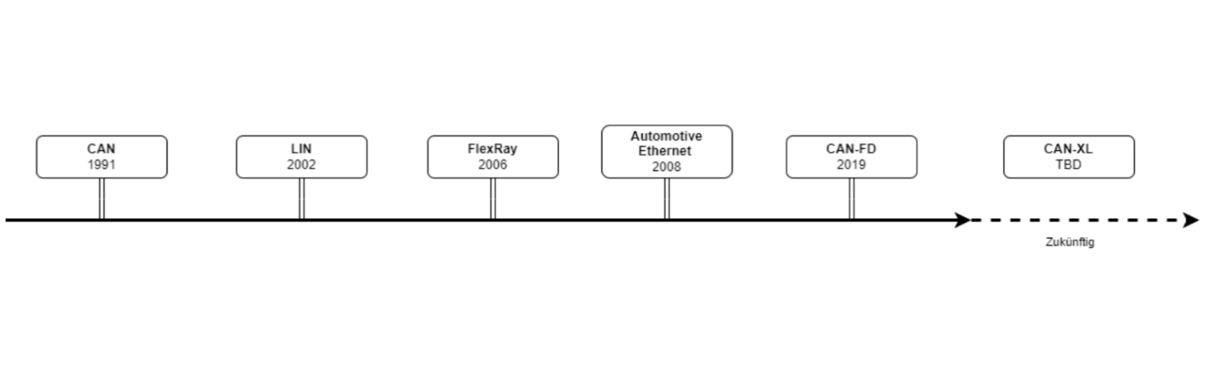
The CAN bus is probably the most widely used bus system in modern vehicles. As shown in the figure below, additional bus systems have been developed over the past three to four decades for special tasks in industry and the automotive sector.

Approximately 15 years after the development of the CAN bus, work began on a more cost-effective variant in the form of the LIN bus, which was introduced in 2002. The LIN bus (Local Interconnect Network) is characterized by its simplicity and low cost. It is mainly used for less complex applications such as the control of comfort systems (e.g., power windows or seat adjustment).

However, with the increasing complexity of vehicles and the emergence of safety-critical systems, it quickly became clear that more powerful bus systems were required. FlexRay, introduced in 2006, was developed specifically for safety-relevant applications such as X-by-wire systems (e.g., brake-by-wire). FlexRay is characterized by a high transmission rate and deterministic behavior, enabling reliable real-time communication.

In 2008, Automotive Ethernet followed, which was originally used for infotainment applications. Compared to previous systems, Automotive Ethernet enables significantly higher bandwidths and plays a crucial role in modern vehicle architectures, particularly with regard to connected and autonomous driving.

In 2012, CAN-FD (Flexible Data Rate) was developed and incorporated into ISO 11898-1:2015 in 2015, representing a further development of the classic CAN bus. CAN-FD enables higher data transmission rates and more efficient communication in order to meet the increasing demands of modern control units.

With CAN-XL, a future standard, further optimization of the CAN bus is currently underway. CAN-XL is intended to provide even higher data rates and additional functions to meet the requirements of the next generation of vehicles.

Despite strong competition in the field of bus systems, particularly in terms of transmission rates, CAN will in all likelihood remain the de facto standard for communication between simple control units for the coming decades. Even though many manufacturers (such as VW and Tesla) increasingly use zonal architectures that require high-speed connections between main control units, it can be expected that simple control units, such as those for power windows, will continue to be implemented using the CAN bus. Even highly modern vehicles such as the ID.7, the Tesla Model Y, or the Audi A5 use it for comfort functions.

Bussysteme im Fahrzeug

Data transfer with the CAN

The CAN bus is a network used for communication between Electronic Control Units (ECUs). In practice, currently only classical CAN and CAN FD are mostly used. The main difference is that, among other things, the bitrate is increased during the transmission of the payload in order to enable a payload that is up to eight times larger. Fundamentally, a CAN message or data frame in any CAN network consists of the following parts; simplified, the relevant ones are:
  • Arbitration field: In addition to the bit that signals the start of a frame, this part contains the 11-bit-long identifier (29-bit extended identifier) of the frame (also referred to as ID), which uniquely identifies a data frame in a cluster. Without extensions, 2048 different identifiers can be used. This ID is used for arbitration, i.e., as a priority for sending messages. The smaller the identifier, the higher the priority of the message. In addition, a bit can be set here that designates a message as an RTR (Remote Transmission Request) instead of a data frame.
  • Control field: The main task of the control field is the transmission of the Data Length Code (DLC), i.e., the specification of the length of the payload.
  • Data field / payload: The data field (0–8 bytes), or in the case of CAN FD (0–64 bytes), is responsible for the actual transmission of information. The information being transmitted can be defined freely.
  • CRC field: CRC (Cyclic Redundancy Check) bits are used to determine whether a message has been transmitted correctly.
  • Acknowledge field: Here, a receiving node confirms that it has received the message correctly (by setting a dominant bit).
  • EOF / IFS: EOF (End of Frame) marks the end of the frame and consists of 7 recessive bits. IFS (Interframe Space) is the waiting time between two frames during which the bus remains idle in order to avoid collisions.
The steps shown here are simplified and do not cover steps that are implemented in hardware or software by CAN transceivers. In practice, the transmission of a piece of information via the CAN bus could look as follows: The odometer reading of a vehicle is transmitted via the CAN message with the ID 0x123. The encoding could be as follows:
  • ID: 0x123 (odometer message)
  • Data field (8 bytes): 00 00 1F 40 00 00 00 00
Here, bytes 2 and 3 (in this case 1F 40 in hexadecimal format) could represent the odometer reading in kilometers. To calculate the actual value, this hexadecimal value is converted into a decimal number: 1F40₁₆ = 8000₁₀ (corresponds to 8000 km) Multiplexing is also often used, in which part of the message acts like an additional part of the ID. For example, 00 in the first data byte could signal the odometer reading, 01 the outside temperature, and 02 the fuel level:
  • ID: 0x123 (odometer message)
  • Data field (8 bytes): 02 00 11 A8 00 00 00 00
In this way, the fuel level could be transmitted: 11A8₁₆ = 4520₁₀ (corresponds to 4520, or 45.20 liters) In this case, the control unit would have to interpret the corresponding data format depending on the value of the first byte. This means that even with such a comparatively simple data structure, complex transmissions are possible. In practice, however, the processing of such data proves difficult for beginners working with CAN data.

The speedsignal difference

As one of the leading companies in the field of CAN data processing in Europe, we at speedsignal GmbH therefore offer solutions that, for example, output simple analog signals. We provide over 25 years of experience in software and hardware in this field so that you can focus on your core business. Most of our solutions are available as plug&play products in our Shop, while more specialized solutions, for example for public authorities , are available in consultation with our competent and friendly sales team..

WordPress Cookie Notice by Real Cookie Banner